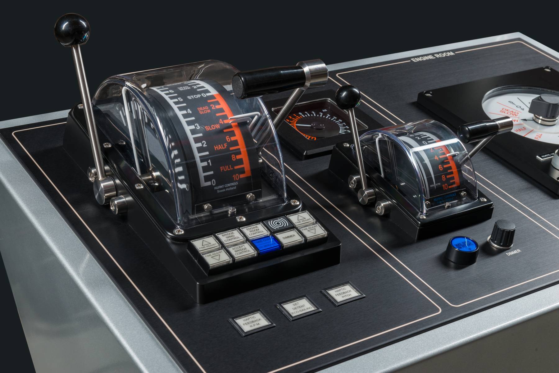
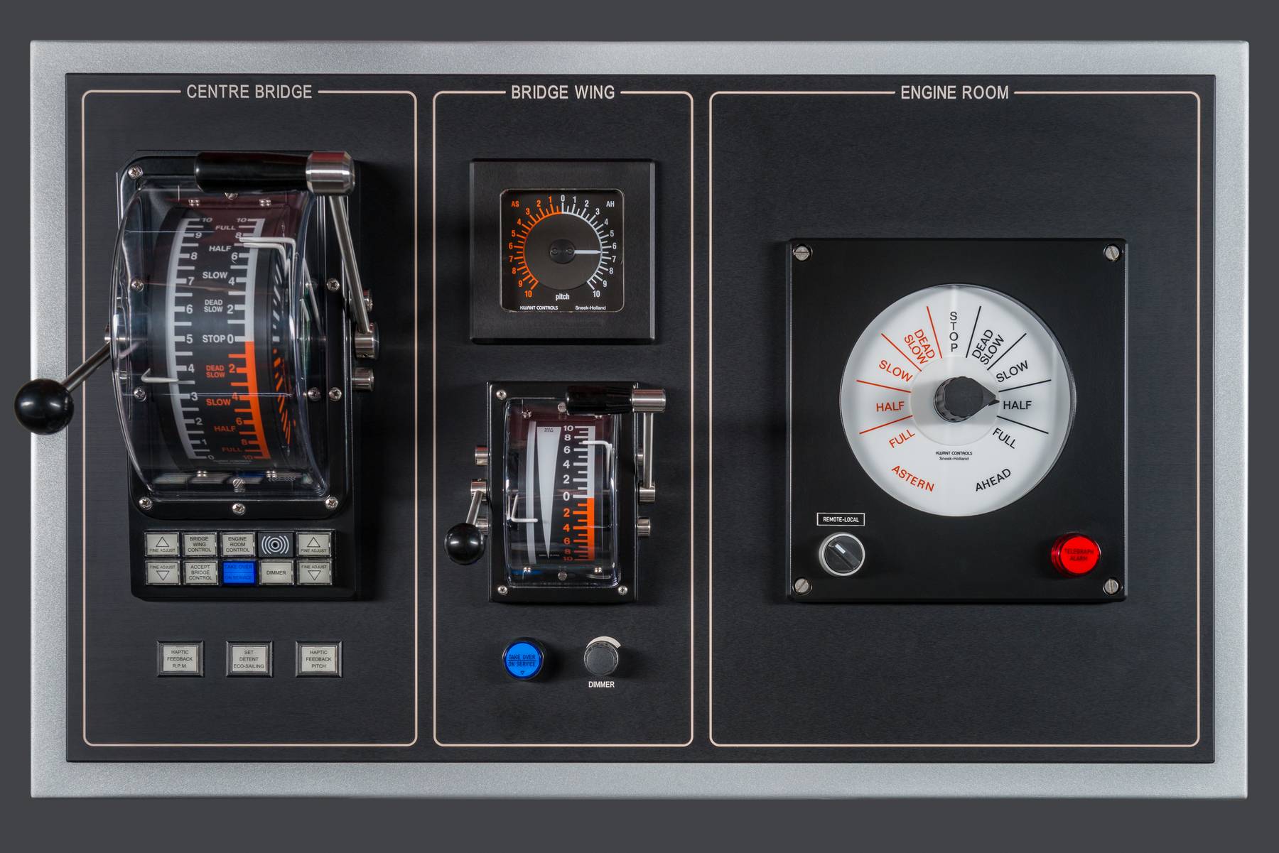
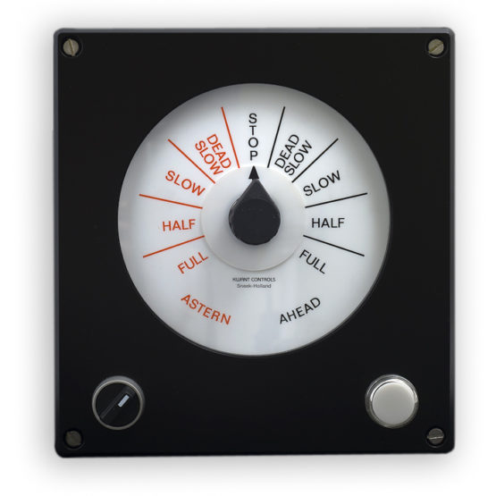
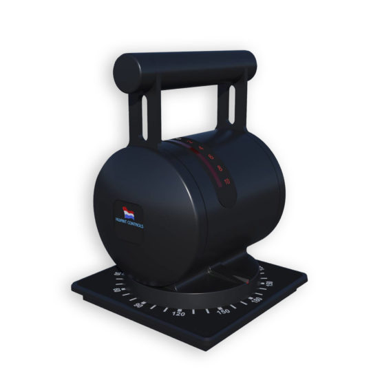
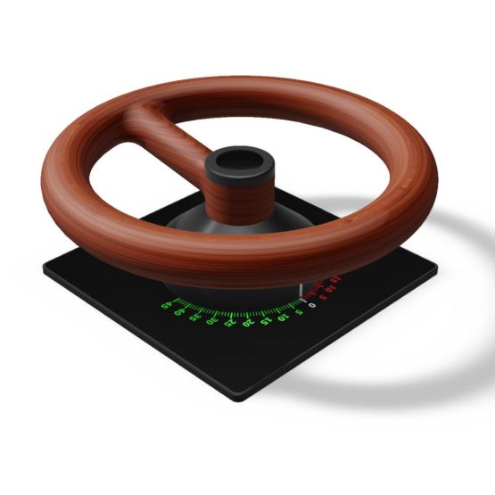
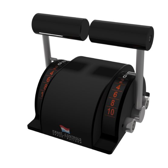
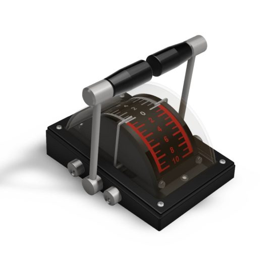
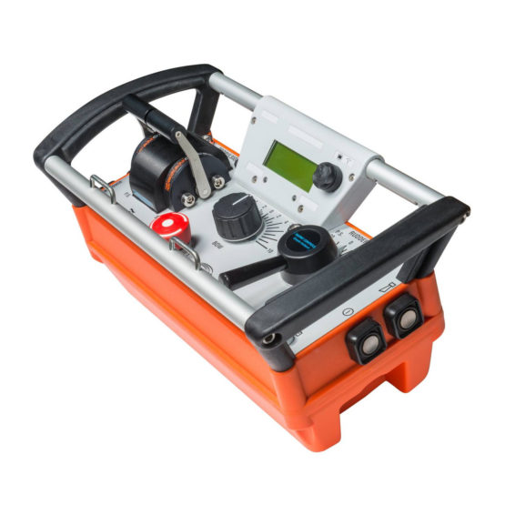
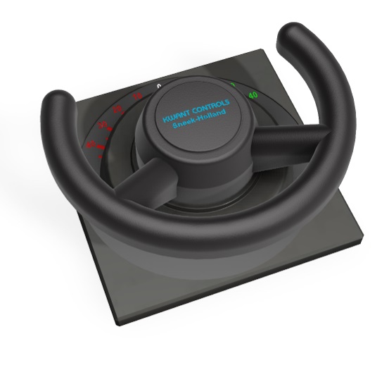
The core business of Kwant Controls is the design and manufacturing of various types of control units for the electrical remote control of practically all kinds of propulsion and steering devices, such as: traditional main engine/clutch/CPP-FPP shaft lines, tunnel thrusters, azimuthal thrusters, rudders and water jets.
Products
Specs
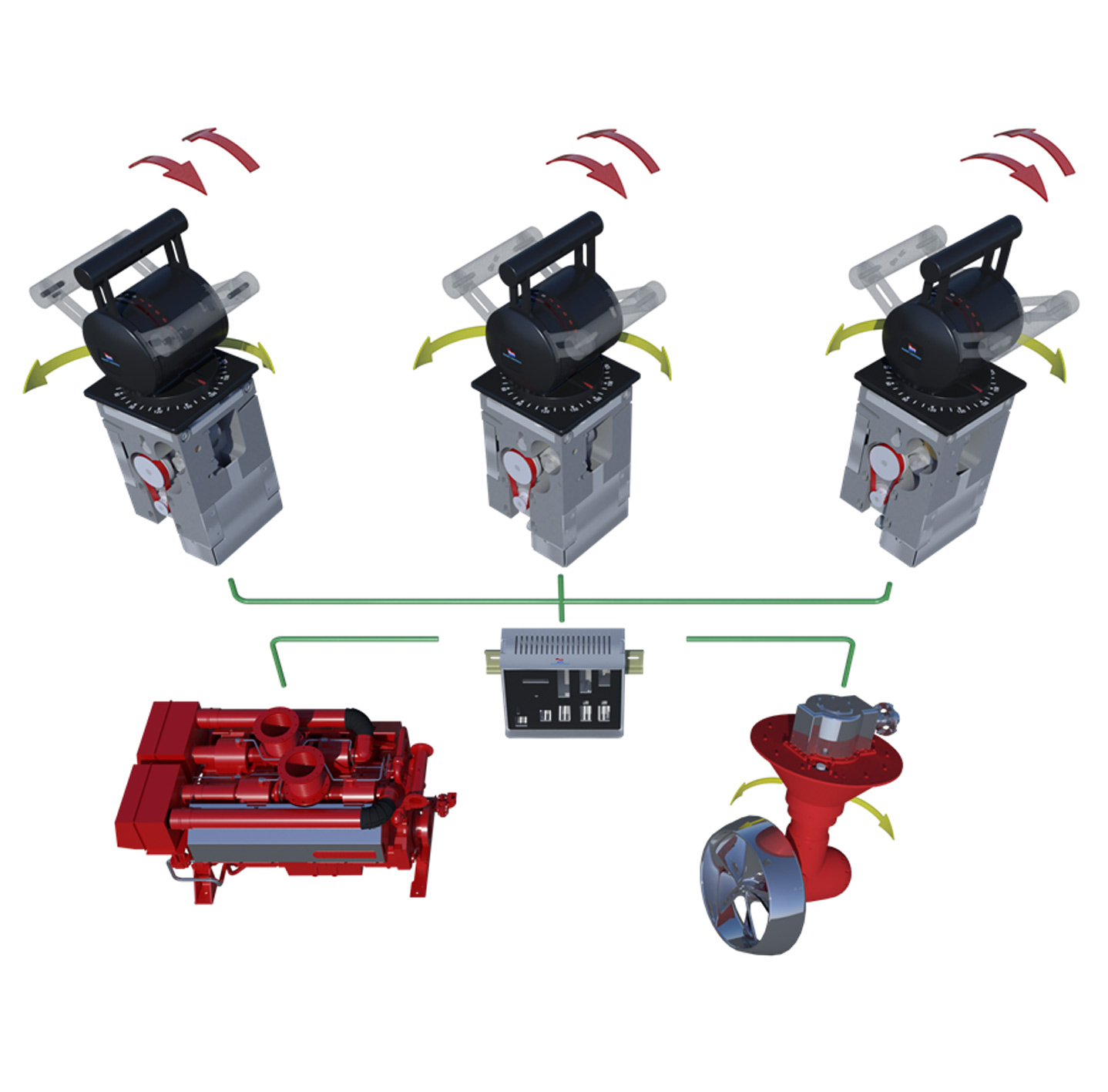
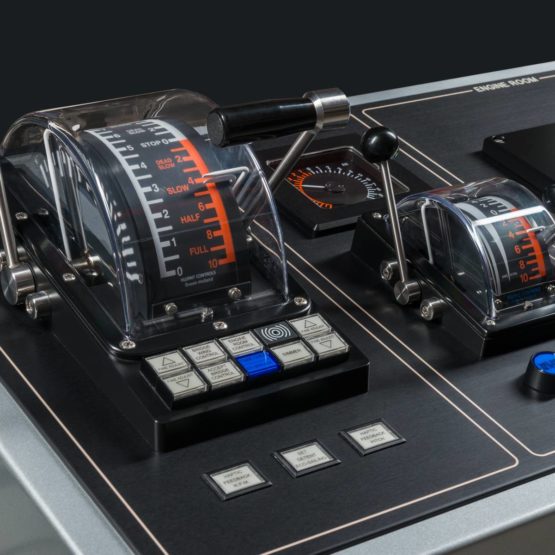
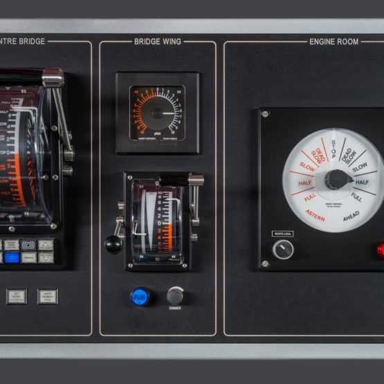
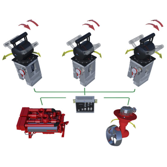
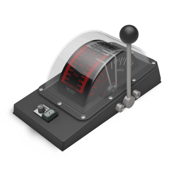
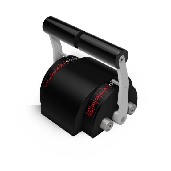
This latest generation of electric shaft systems is based on stepper motor driven levers and CAN bus technology. It merges the traditionally separated telegraph- and electric shaft systems into one combined system, thus providing much improved flexibility and reduction of installation time and cabling costs. The application of stepper motors introduces a number of features such as programmable detents, haptic feedback and very accurate fine adjustment that could not be realized with the traditional DC-motor technology. The CAN bus is a widely spread and rugged serial bus system that has its roots in the automotive industry where extremely severe demands must be fulfilled. The electronics have been completely distributed over the operating positions, thus eliminating the traditional central cabinet.
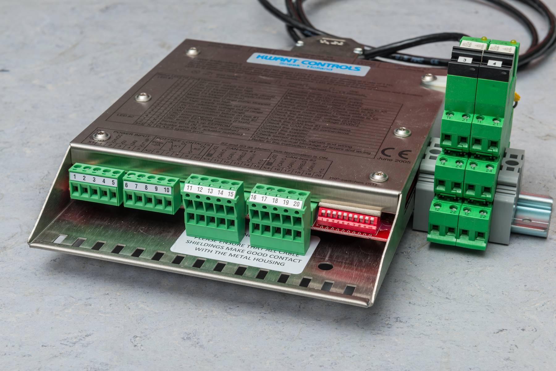
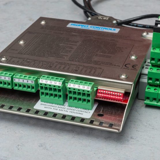
The electronic module that interfaces the control units to the CAN-bus is known as the CUBI, short for Control Unit to Bus Interface. The basis for the communication with the module is the CAN-open protocol. The CUBI module contains a single printed circuit board and can handle two servomotor controllers and eight digital in- and outputs, while providing two CAN-bus transceivers for bus redundancy. The CUBI module has a seawater proof stainless steel housing that can easily be clicked on a 35/7.5mm DIN-rail according to EN-50022A. Polyurethane based coating is protecting the sensitive parts of the printed circuit board.
For the connection to the ship’s cabling, pluggable connectors are used. This eases the installation and replacement of the module. Cables with D-Sub connectors are used for the lever side of the module.
Each Elas-5 system can handle a maximum of eight control units (nodes), a maximum of four of these systems can be tied together thus allowing a maximum of 32 control units to operate in full synchronicity.
The Elas-5 system has been type-approved by the following leading classification bureaus: ABS, BV, CCS, DNV, GL, LRS, NKK , RINA and RMRS.
Options
- Central take over.
In a standard system, selection of the master lever is done by means of a simple illuminated pushbutton, wired directly to the corresponding CUBI module (= local take over). In case the position take over has to be achieved by means of another control system, the pushbuttons are replaced with potential free contacts (one for each position), that can all be wired to a single CUBI module. - Tandem mode.
Also known as ‘one lever mode’, this option allows the operator to control up to four propulsion plants with just one lever, for more operating comfort. To achieve this, the CAN-buses of Port side and Stbd side systems are linked together by means of an isolated CAN repeater. - Electrical fine adjustment.
For events like convoy sailing, which require very precise setting of the engine speed or propeller pitch, the manual lever movement is often too course. To overcome this problem, the system can be expanded with pushbuttons for electrical fine adjustment that will move the lever in the desired direction very slowly. The CUBI module now uses modified micro-stepping to achieve optimum precision. - Haptic feedback.
To limit the allowed operating range of a control lever, a so called ‘haptic feedback’ can be activated to prevent the lever from being moved outside this area. The servomotor will try to push the lever back, causing a vibration in the lever to let the operator know that he is leaving the safe operating area.
- Sub-telegraph commands.
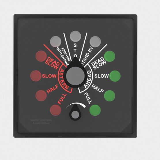
Up to three illuminated pushbuttons may be connected to transfer and acknowledge the so called sub-telegraph commands such as ‘stand by’, ‘finished with engine’ and ‘at sea’. Sub-telegraph commands are always sent from bridge to ECR or ER. An intermittent audible alarm (1 Hz) is used to distinguish from the propulsion telegraph alarm.
- Programmable detents.
The servomotors that are used for moving the control lever when a control unit is in slave mode, can also be used to create the feeling of a mechanical detent (palpable stop) when the control unit is in master mode. By default, there is a detent in the neutral position, others can be programmed e.g. at the clutching positions or optimum engine RPM. Another example: when in telegraph mode, all commands will now have detents in the centre of each command field. A maximum of 16 detents can be programmed for each motor. - External signals.
Two inputs for external 0-20mA signals are available, from e.g. a joystick- or speed pilot system. This allows automatic lever line-up with the external signal source and provide bumpless switching over from lever to external control and vice versa.

