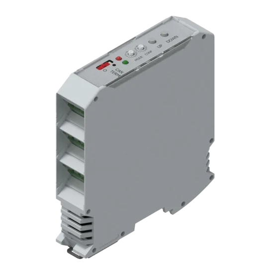
Description
Specs
The dimmer circuit is wired in series with the lamps and acts as a controllable power resistor. Each dimmer circuit has a pre-set potentiometer for adjusting the minimum brightness level of the lamps. If the dimmer circuit is placed in the positive supply lead of the lamps, it will source the lamp current. This is referred to as a P-type circuit. If the dimmer circuit is placed in the negative (minus) supply lead of the lamps, it will sink the lamp current. This is referred to as an M-type circuit.
Options
The electronic dimmer is available in three different executions:
- Execution 1: ED-MM = both circuits are of the M-type;
- Execution 2: ED-PP = both circuits are of the P-type;
- Execution 3: ED-MP = first circuit is of the M-type, second circuit is of the P-type;
- Execution 4: QED-MMMM = all four circuits are of the M-type;
- Execution 5: QED-PPPP = all four circuits are of the P-type;
If more than two groups of lamps have to be dimmed, a central multi-section potentiometer is used, available in 4, 6 or 10 gangs, each gang serving 1 dimmer circuit. Each dimmer power module is now supplied with a pluggable terminal block instead of the dual section potentiometer. The suffix ‘S’ (for Separate) is added to the type ID of the dimmer module (for example: ED-MM becomes ED-MMS).

